2
machining phases
6
operations programmed
3D
validated before cutting
This project was carried out in industrial partnership within the Arts et Métiers framework. The objective: produce a complete CAM-based manufacturing study for a real mechanical component — from functional analysis through to a production-ready machining program that could be handed directly to a machinist.
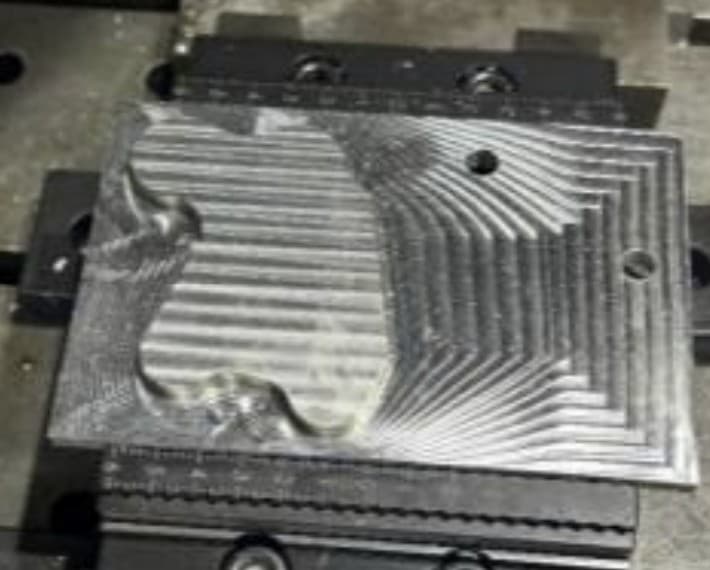
Not a simulation exercise. The part is real, the tolerances are functional, and the program runs on a real CNC machine.
Functional analysis
Structured analysis of the part within its assembly: primary and constraint functions, interfaces with neighbouring parts, surfaces that matter for function. This determined which dimensions needed tight tolerances and Ra requirements — and which didn't.
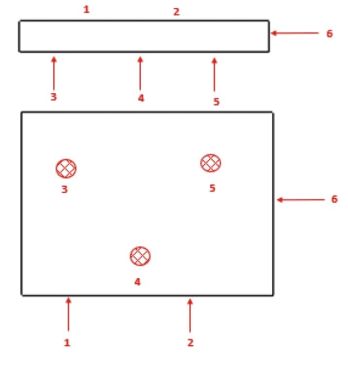
Isostatism — fixture design
3-2-1 positioning scheme for Phase 1: three contact points on the primary face, two on a perpendicular face, one stop on the orthogonal axis. All six degrees of freedom eliminated. For Phase 2, the part re-references from machined surfaces produced in Phase 1, ensuring the tolerance chain propagates correctly.
CAM Phase 1 — roughing and primary features
Surface facing (D12 end mill), 3D pocket milling, centre drilling + drilling D15 and D10. Each operation defined with tool geometry, cutting parameters (Vc, fz, ap), and approach/retract strategy.
CAM Phase 2 — finishing and secondary features
Pointing and drilling (D15, D10.5), pocket operations (D6 and D12 end mills), circular milling (fraisage circulaire), contour milling. The part is repositioned from the Phase 1 datum surfaces.
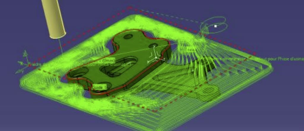
3D simulation and validation
Full simulation of both phases before any metal was cut. Tool paths verified for collisions, gouges, and clearance. Cycle time estimated per operation. No surprises on the machine.
Industrial deliverables
Complete manufacturing dossier: part drawing with full GD&T annotation, process plan (gamme d'usinage) for both phases, FAO files and cutting conditions by operation, quality control plan with instrument specification and inspection frequency.
The program was 3D-simulated and validated. No metal was cut on a guess — every tool path was verified for collisions, gouges, and cycle time before the machine was loaded.
What this demonstrates
A CAM project is a design project as much as a manufacturing one. The machining programme is the output, but the engineering is in the decisions before the first operation: which surfaces are functional, how the part is fixtured, how errors from Phase 1 propagate into Phase 2. This project produced a complete industrial dossier — not a screenshot of a CAM interface, but a document a machinist could pick up and use.