3
manufacturing phases
AlSi7
alloy
H7
bore tolerance class
5
machining operations
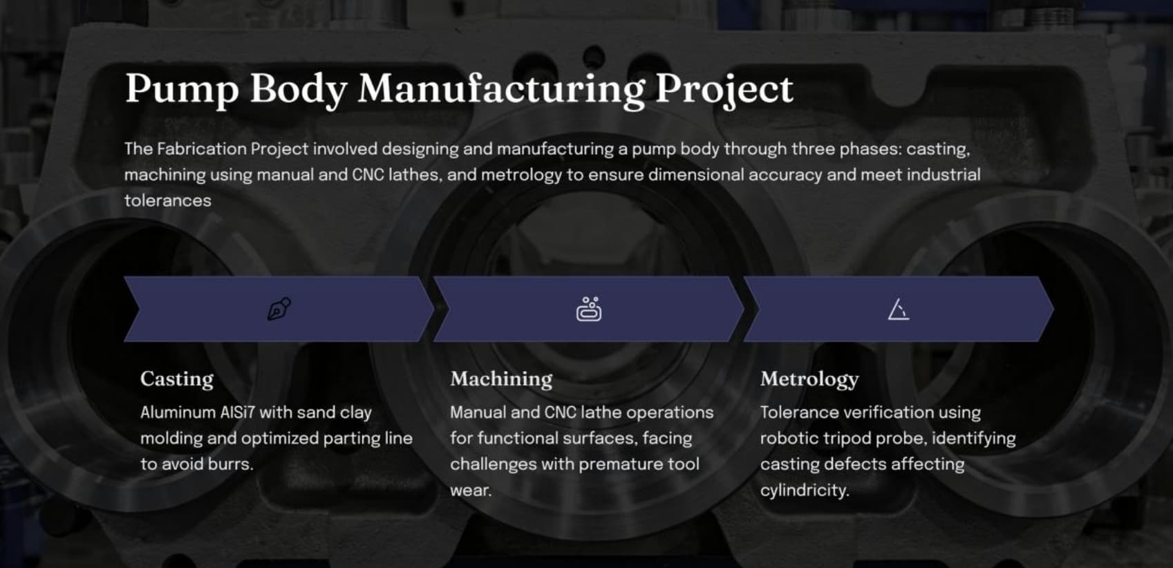
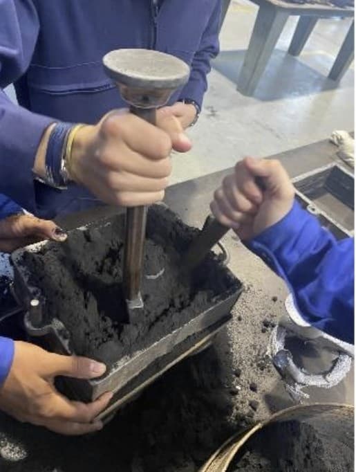
A pump body is a deceptively simple part — until you make it. This project covers the complete manufacturing cycle of an aluminium pump body in AlSi7: sand casting, CNC machining on a Mazak lathe, and dimensional verification with a robotic CMM probe.
Each phase has its own failure modes. And those failure modes are connected.
Phase 1 — Sand casting (AlSi7)
Mould design decisions: parting line to minimise undercuts, 1–3° draft angles on all vertical faces, 2–3mm machining allowance on critical surfaces, sand core for the internal cavity. The raw cast parts showed Ra ≈ 12µm surface roughness — expected. Some parts showed cold shut defects on thin sections.
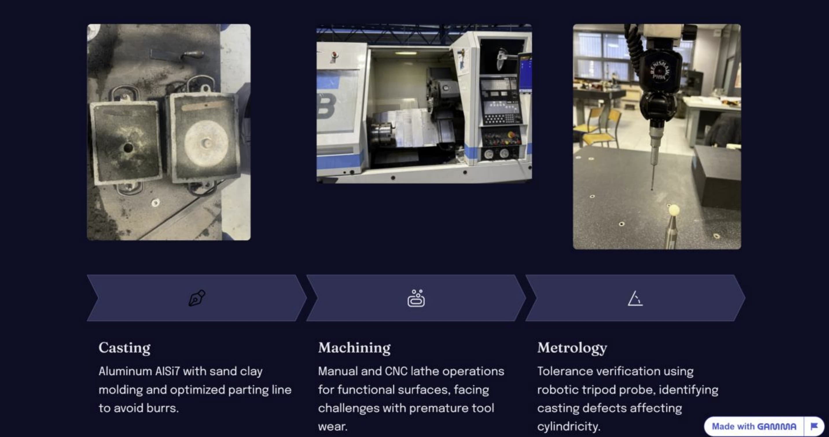
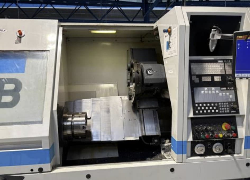
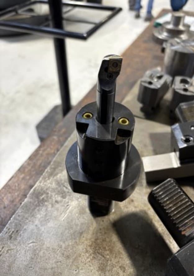
Phase 2 — CNC machining (Mazak lathe)
Five operations in sequence: facing (datum reference face A), external turning to tolerance, boring to H7, threading for port connections, and finish turning to Ra ≤ 1.6µm. Challenge: premature tool wear on some parts, traced to harder inclusions from cold shut zones in casting.
Phase 3 — Metrology (robotic CMM)
Dimensional verification with a tripod CMM probe: bore measured at 3 axial positions × 4 angular orientations for cylindricity, perpendicularity of bore axis to datum face, thread pitch and effective diameter.
The casting choices that determined everything downstream
The mould design is not just a geometry problem. Every decision made at the casting stage has a downstream consequence in machining and metrology.
The cold shut defects that appeared in some parts were a direct consequence of insufficient metal flow velocity into thin sections. Those same defects — harder, more brittle inclusions — caused the premature tool wear observed in Phase 2, which then appeared as cylindricity errors in Phase 3.
The CMM doesn't lie. Cylindricity errors traced back to cold shut defects in casting — the feedback loop was complete and unambiguous.
What this demonstrates
This project demonstrates the manufacturing chain as a system — not as three independent phases. The casting choices propagate into machining difficulty, which propagates into metrology outcomes. Understanding this chain is what separates a manufacturing engineer from someone who can operate each machine individually. The cold shut → tool wear → cylindricity failure sequence was the most valuable lesson: it could not have been seen without running all three phases and closing the feedback loop.