8.5kW
transmitted power
5.5:1
reduction ratio
20,000h
SKF bearing L10 life
1.6
helical contact ratio
Design a single-stage helical gearbox transmitting 8.5 kW at a ratio of 5.5:1 — from functional requirements to a fully specified assembly. The methodology follows AGMA standards throughout.
Gear design
| Parameter | Value | |-----------|-------| | Power | 8.5 kW | | Ratio | 5.5 : 1 | | Material | 35CrMo4 (case-hardened) | | Helix angle | 15° | | Module (normal) | 3 mm | | Centre distance | 156 mm |
Bending stress (Lewis + AGMA correction factors) was verified for pinion and gear, contact stress (Hertzian) checked for pitting resistance over the required service life, with safety factors Sf ≥ 1.2 on bending and Sh ≥ 1.1 on contact. The helical geometry was selected to achieve a contact ratio above 1.6 and reduce noise versus equivalent spur gears.
Shaft design
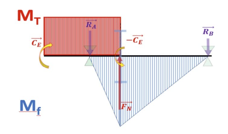
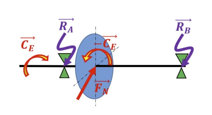
The gear mesh produces tangential, radial, and axial forces on each shaft. Bending moment diagrams were constructed in both planes and combined with torsion.
Shaft diameters were sized with the Tresca criterion and a fatigue safety factor: input shaft (pinion) Ø 35 mm at the gear seat, output shaft (gear) Ø 55 mm at the gear seat.
Bearing selection — SKF
Bearings were selected from the SKF catalogue for a required life L10 ≥ 20,000 h, using a fixed-floating arrangement on each shaft: the fixed bearing (duplex angular contact) reacts axial loads, while the floating bearing (cylindrical roller) accommodates thermal expansion.
Every value connects to the next: gear forces → shaft loads → shaft diameter → bearing bore → SKF reference.
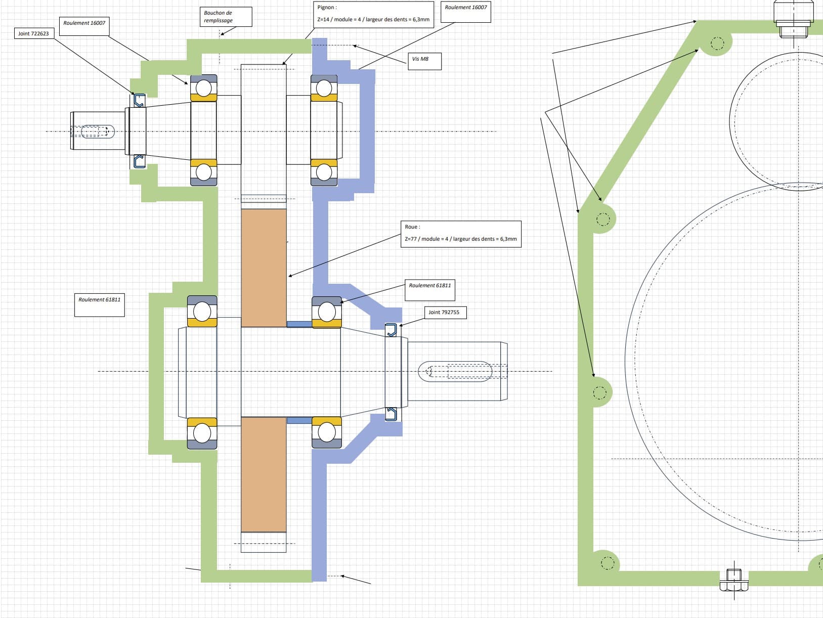
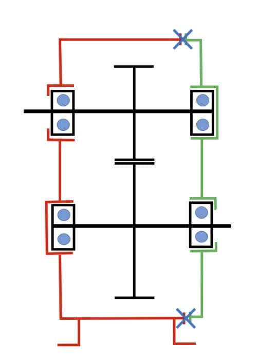
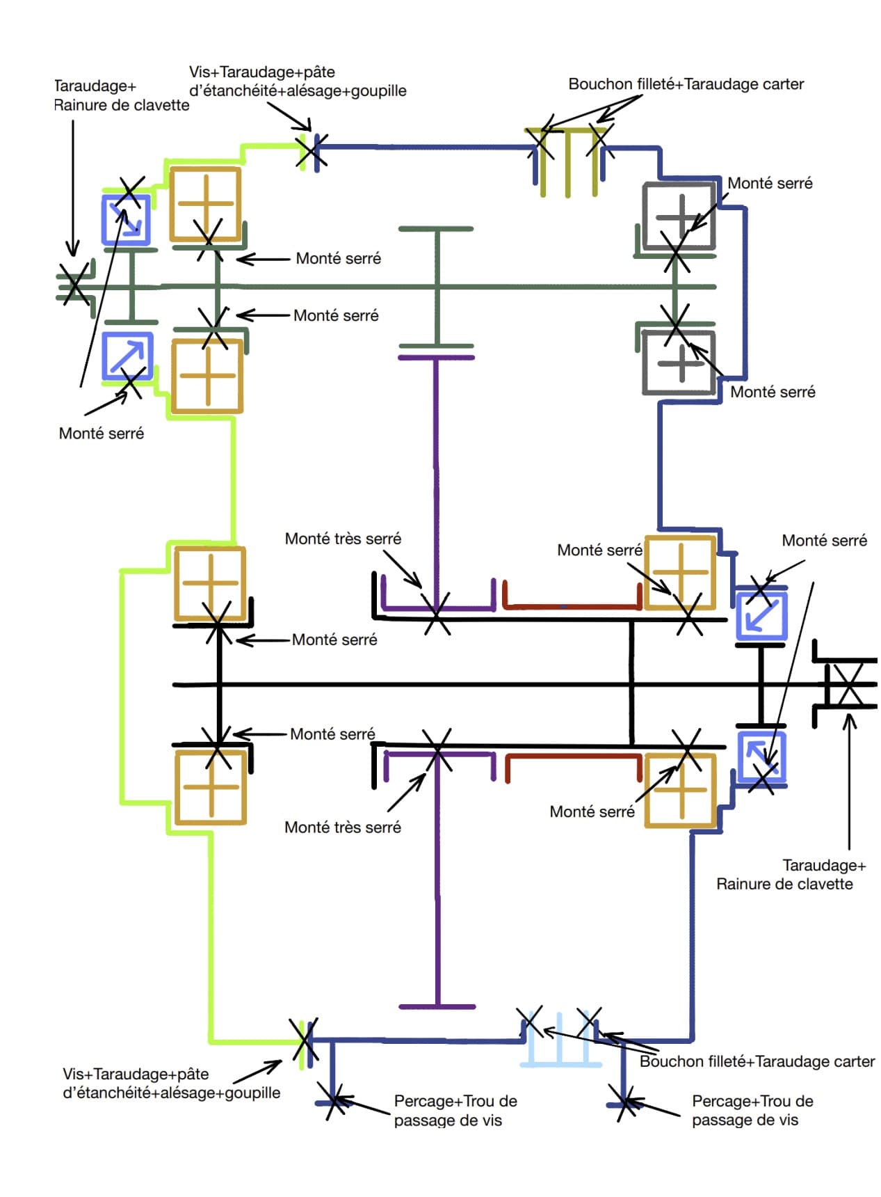
Assembly connections
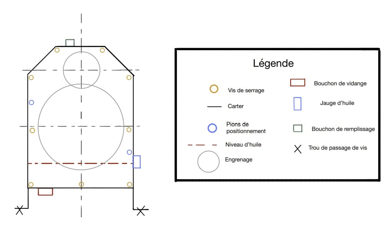
Gear-to-shaft uses an interference fit (H7/p6) plus a key-and-keyway; bearing inner rings use an interference fit (k6 on shaft); the housing cover is secured with threaded fasteners, an O-ring seal, and drain/fill plugs. Lubrication is by oil splash, level set to 1/3 tooth depth immersion on the large gear.
What this demonstrates
Every value in this design connects to the next: gear forces → shaft loads → shaft diameter → bearing bore → SKF reference. This end-to-end traceability — not isolated calculations — is what AGMA-based mechanical design requires.