21
kN peak inertial force
650×
reduction after balancing
360°
crank cycle modelled
2
machining phases (PFMC)
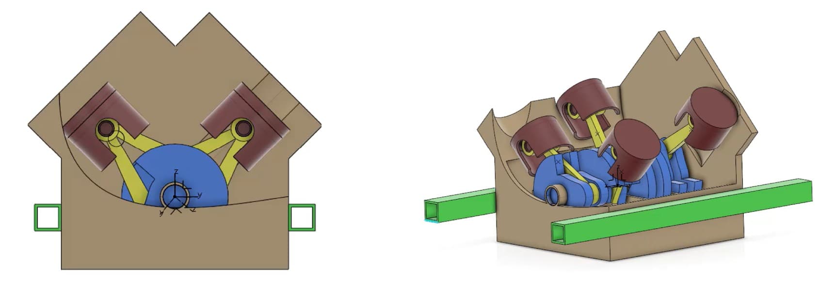
This project studies a V4 engine at 90° — a four-cylinder engine in a V configuration with a 90° angle between the two cylinder banks, an architecture used in performance motorcycles and sports cars. The 90° V-angle has specific dynamic properties that make it naturally balanced in some orders but not others — which is precisely what this project analyses, from pure kinematics through to the machining of one of its parts.
Part 1 — Kinematics
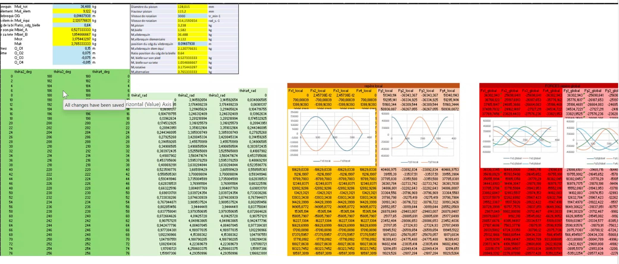
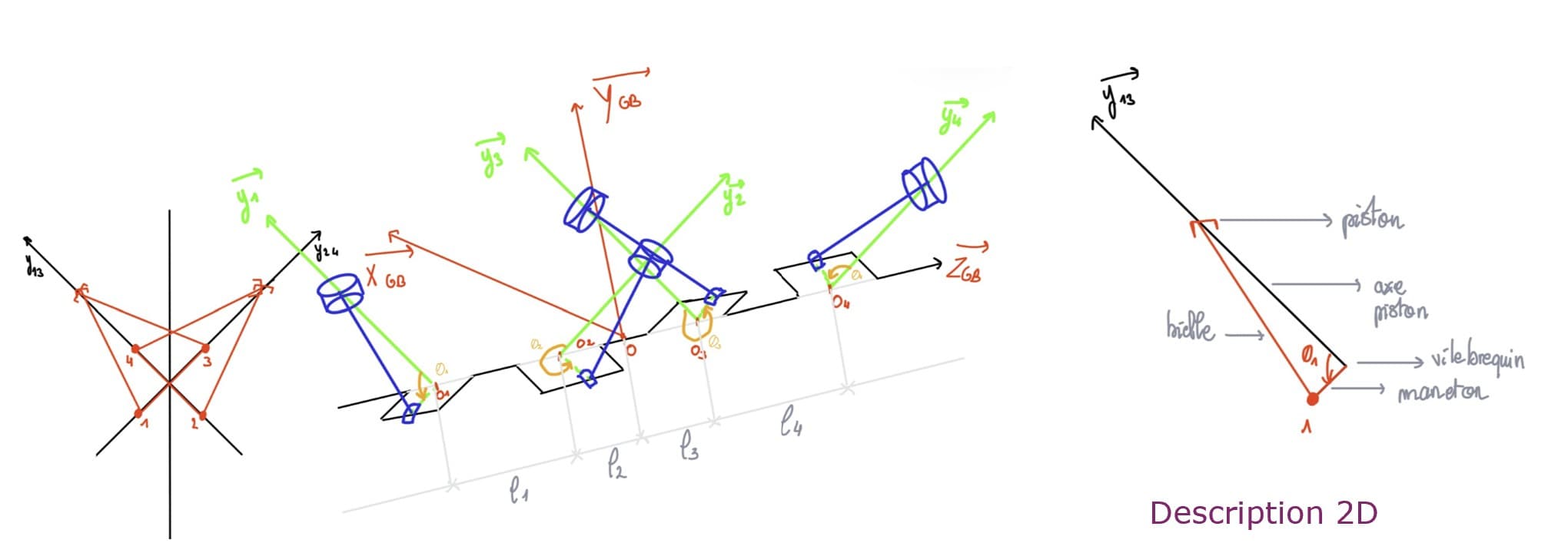
The mechanism is modelled with the complete crank-connecting rod geometry: crankshaft (input, constant angular velocity), two pairs of connecting rods at 90°, and four pistons in translational motion.
Joint positions, velocities, and accelerations were computed analytically for every 2° of crank rotation over a full 360° cycle and tabulated in a calculation spreadsheet — the foundation for everything that follows.
At 90° V-angle, the two cylinder banks produce force pulses with a defined phase relationship — the starting point for the dynamic analysis.
Part 2 — Dynamic Analysis
Using Newton's second law applied to each moving element, the inertial forces generated over one full crank cycle were computed. The oscillating masses (pistons + connecting rod portions) produce forces transmitted directly to the engine block: first-order forces sinusoidal at engine rotation frequency, second-order forces at twice that frequency.
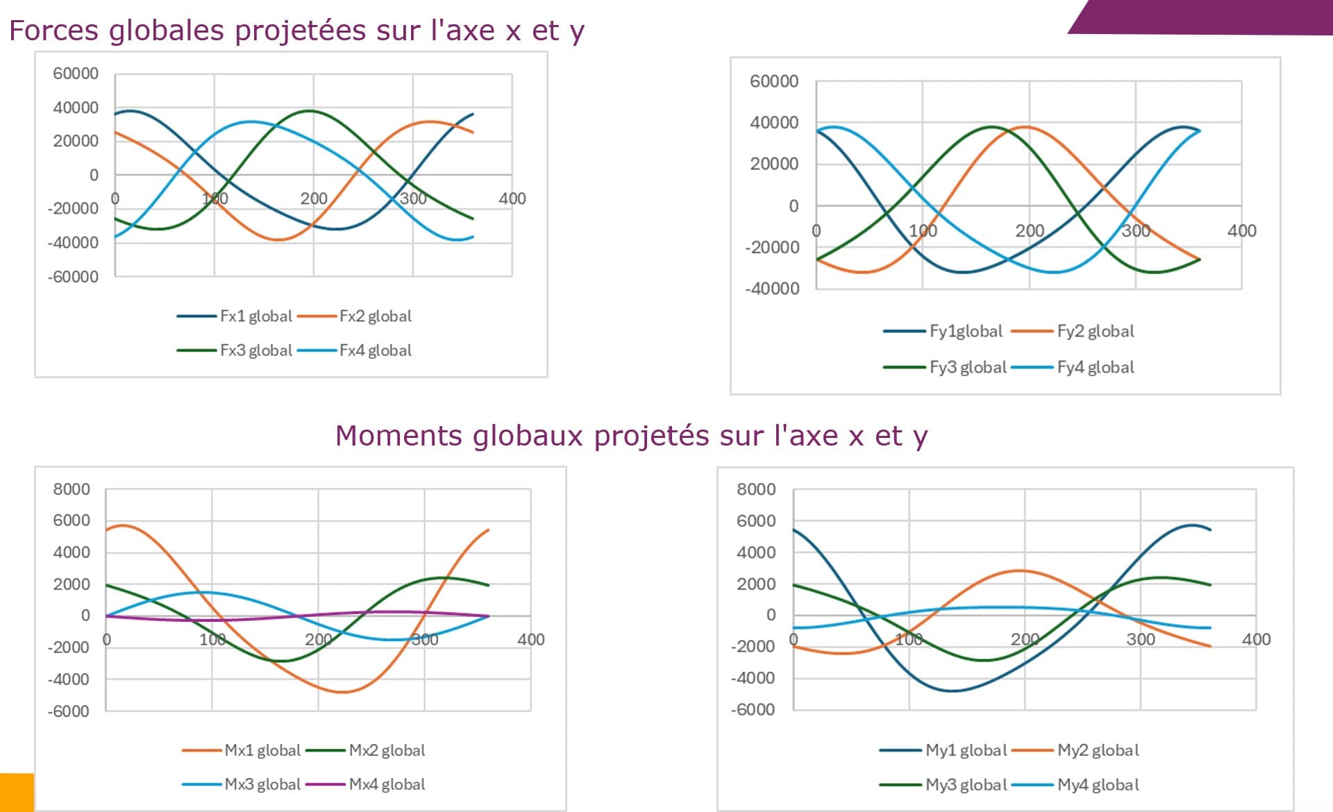
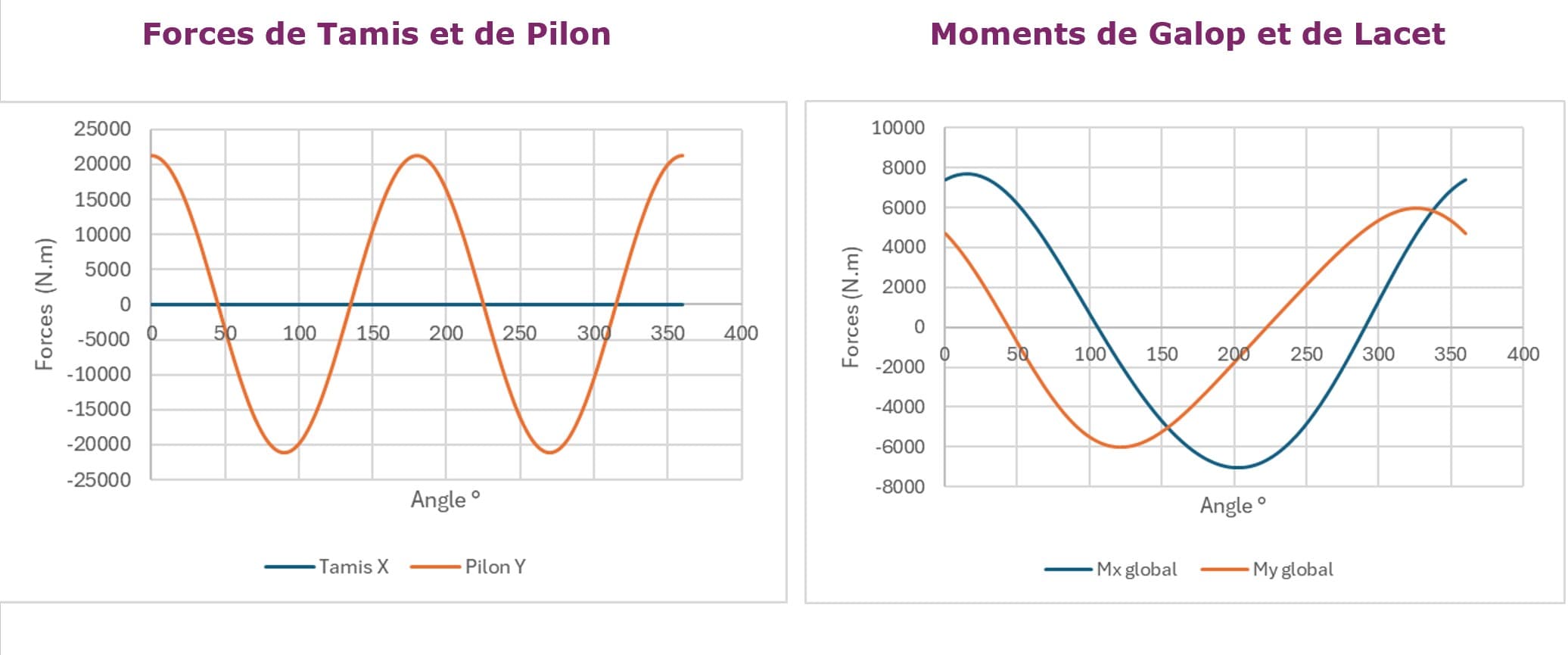
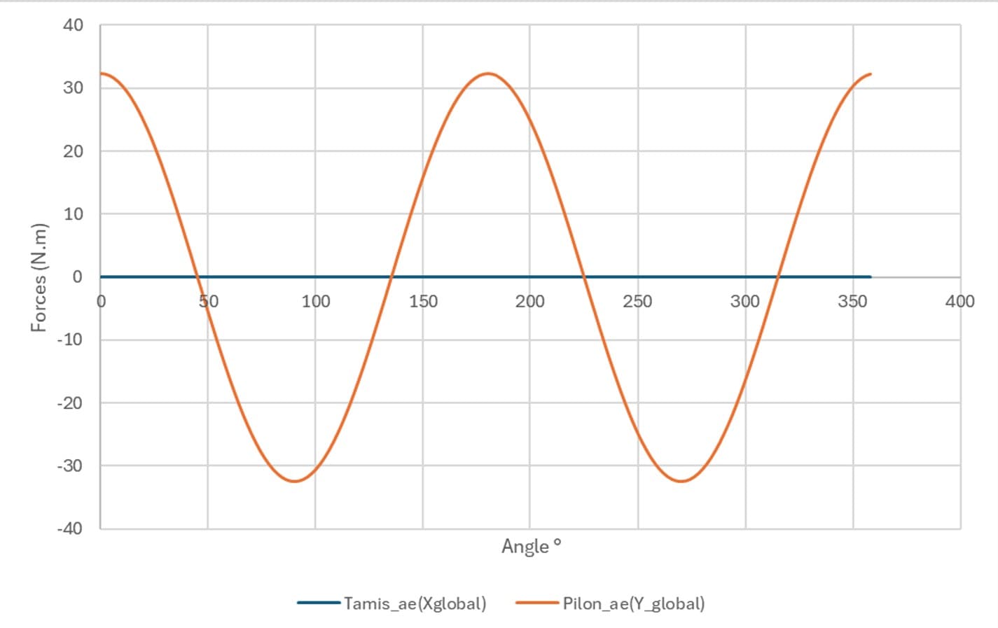
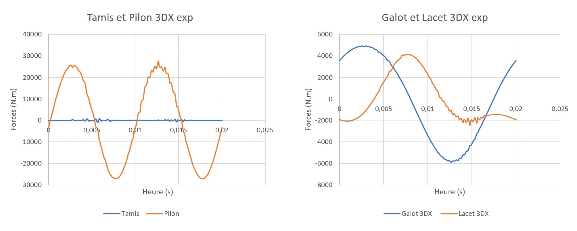
The global moments on the engine mount — Galop (pitching) and Lacet (yawing) — were computed from the force and position data. Both are periodic, with significant amplitudes that would cause vibration if left uncontrolled.
Part 3 — Counterbalancing
From ±21 kN to near zero — a counterbalancing strategy verified analytically, not assumed.
To reduce the transmitted forces and moments, a counterbalancing strategy was developed — adding counterweights to the crankshaft at calculated positions.
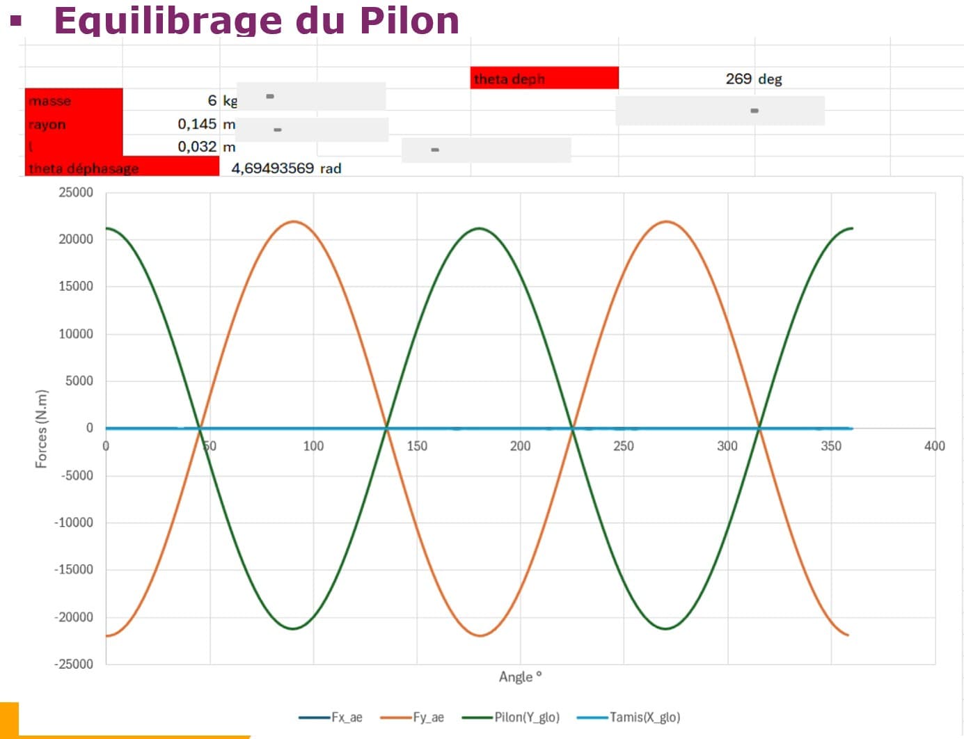
Optimal counterbalance parameters: mass 6 kg, radius 0.145 m, phase offset 4.69 rad (≈ 269°).
Unbalanced
±21 kN
Residual inertial force transmitted to the engine block
Balanced
≈ 0 kN
After optimal counterweight placement on the crankshaft
Part 4 — Machining Study (PFMC)
Part V4a90 was positioned and clamped using the isostatism method: 3-2-1 positioning (3 points on the reference face, 2 on a perpendicular face, 1 on an orthogonal stop), with clamping force calculated to exceed the maximum cutting force without over-constraining the part.
The machining sequence was defined to propagate the tolerance chain correctly: facing operations to establish reference datums, external turning and shouldering, milling and pocket operations, drilling and boring of functional surfaces, then finishing passes to final tolerances. For each operation, cutting parameters were derived from material grade, tool coating, required surface roughness (Ra), tool life (Taylor's equation Vc × T^n = C), and machine power limits.
What this demonstrates
From mechanism kinematics to inertial force computation, counterbalancing optimisation, and CNC machining — this project covers the full mechanical engineering analysis chain applied to a real engine architecture. The forces involved (21 kN) are physically meaningful, and the counterbalancing result is verified analytically, not assumed. The animated simulations below show the mechanism and the machining sequence in motion.